Material Translation:
From Carbon to Composite
Design for Manufacturing (DFM)
Structural Optimization
FEA Collaboration
Production Validation
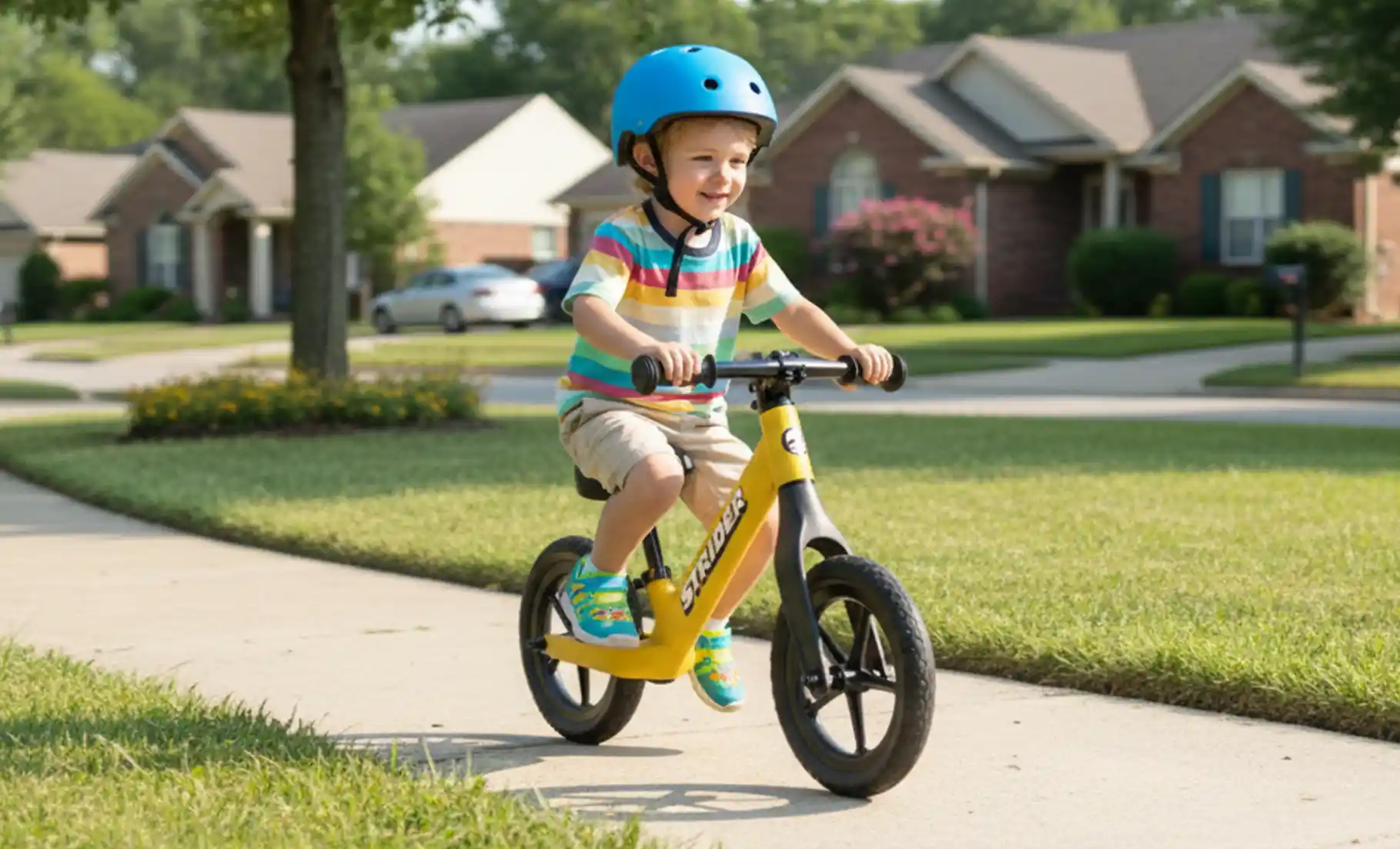
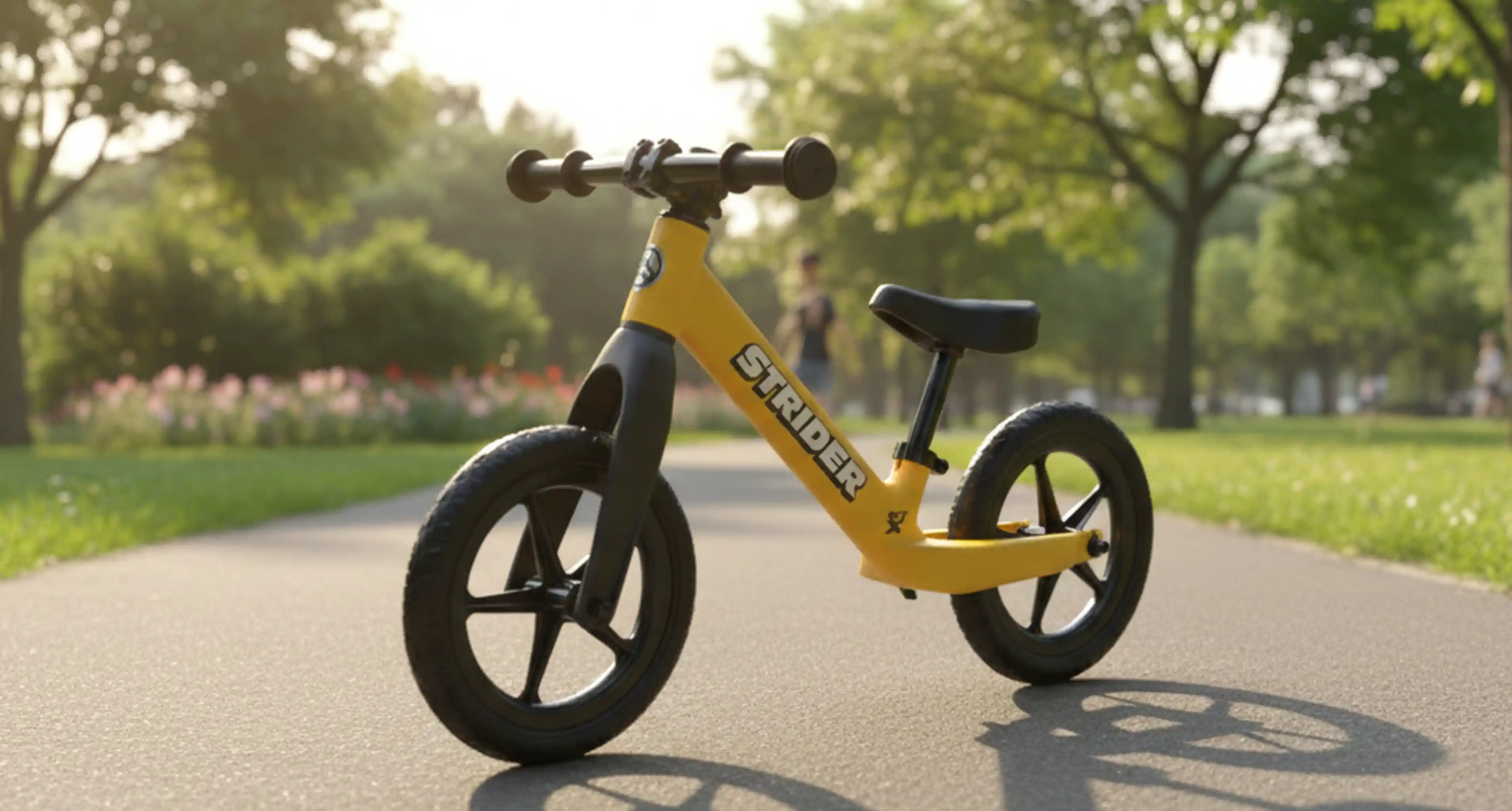
The Challenge: Democratize the high-performance aesthetic of Strider’s flagship Carbon Fiber balance bike
by translating it into an injection-molded design.
This project bypassed the traditional sketching phase, moving directly into rigorous 3D surface modeling.
The goal was to capture the seamless, organic "flow" of carbon fiber while adhering to the strict draft
and wall-thickness requirements of injection molding.
Working in lockstep with engineering, we utilized Finite Element Analysis (FEA) to iterate on the internal
ribbing structure. This ensured the final design met or exceeded Factor of Safety requirements without compromising
the fluid exterior lines—proving that robust engineering and beautiful design can exist in the same part.
The challenge was to translate the premium, seamless aesthetic of Strider’s carbon fiber
flagship into a high-volume injection-molded platform. This wasn't a simple conversion;
carbon fiber permits geometries that are impossible in rigid plastic molding.
To solve this, we approached the development in three distinct phases, utilizing advanced
Class-A surfacing techniques to strictly manage curvature continuity and light reflections.
This iterative process allowed us to maintain the organic "flow" of the original design
while rigorously adhering to the draft angles and parting line constraints required for mass production.
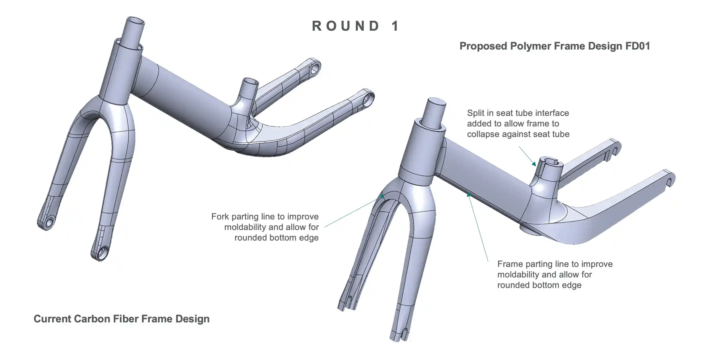
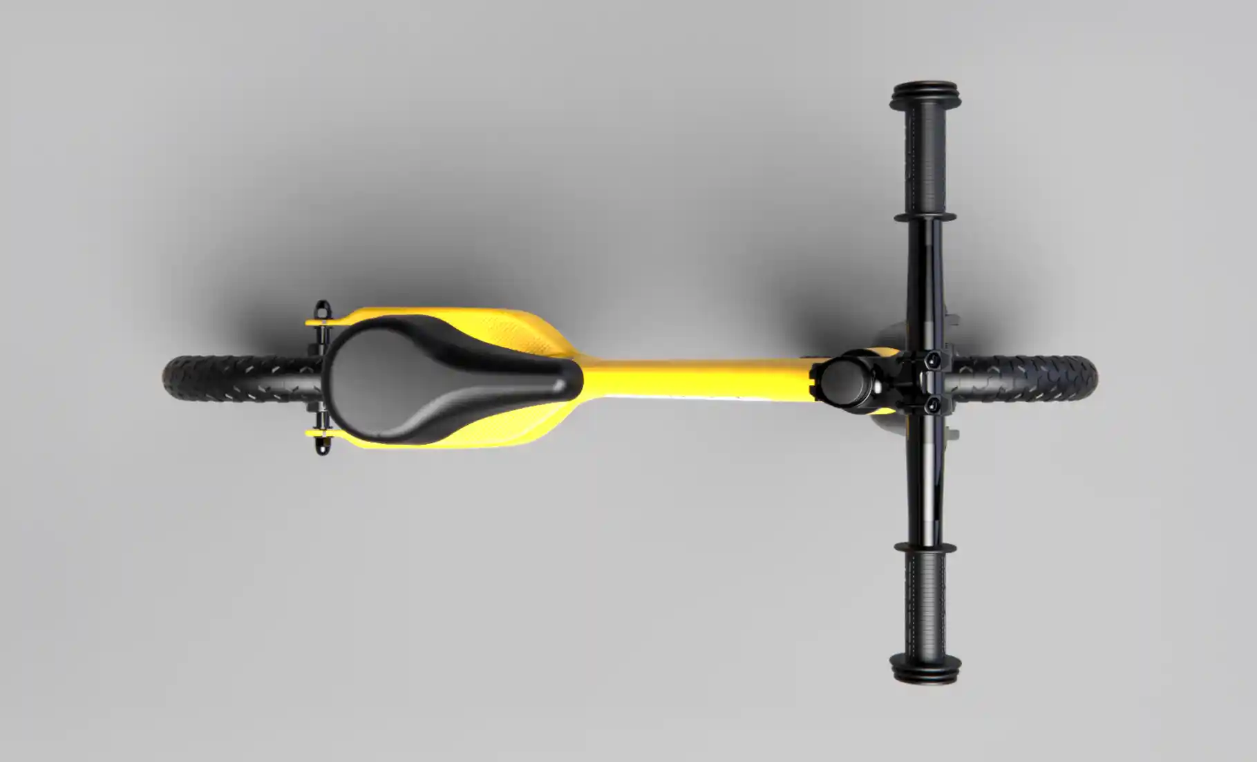
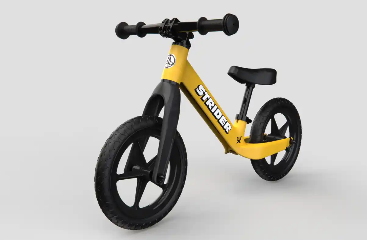
Round 1: Volume & Stance. Establishing the primary "bones" of the bike. The focus here was capturing the aggressive silhouette of the carbon fiber original without worrying about surface transitions.
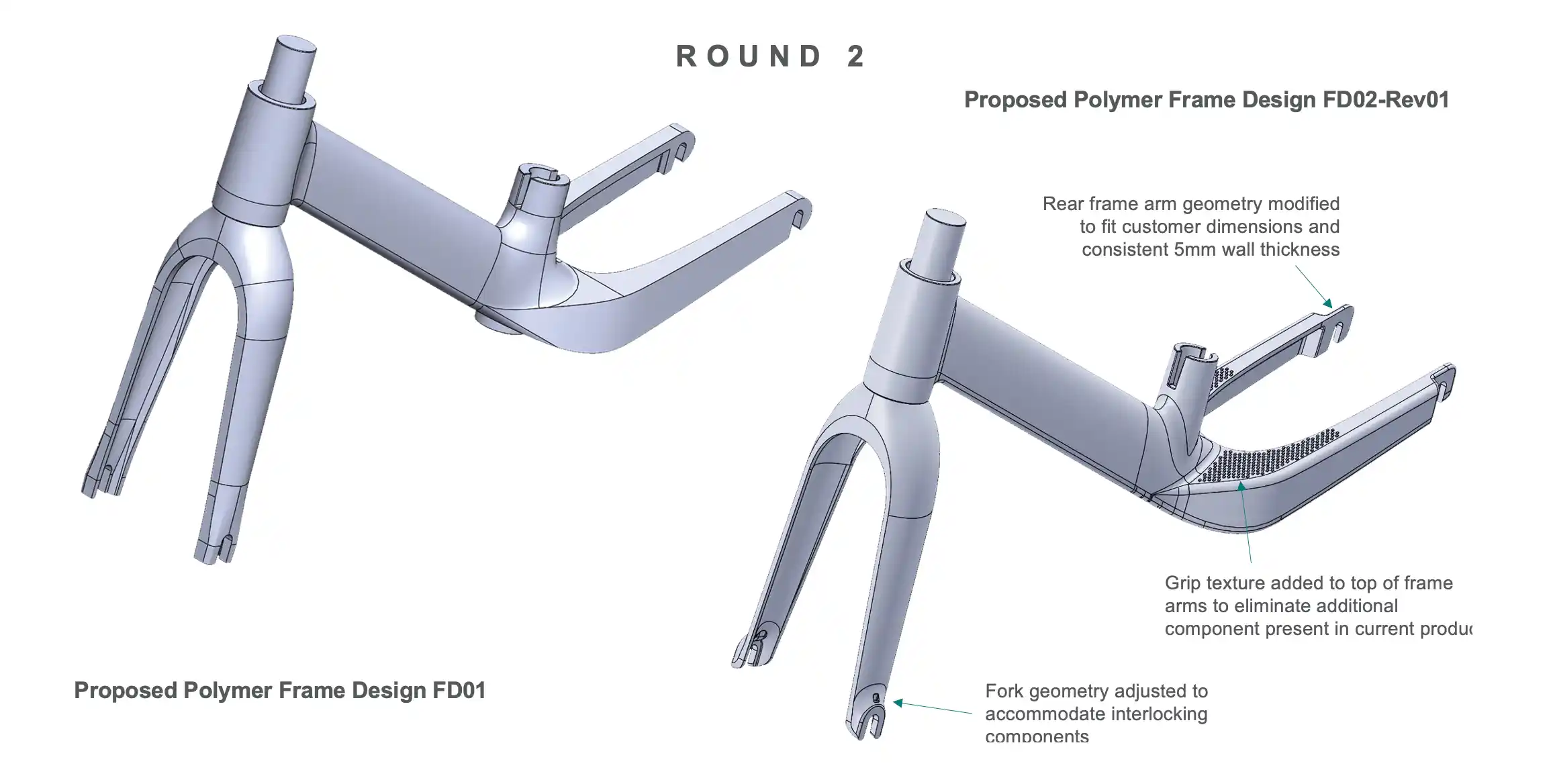
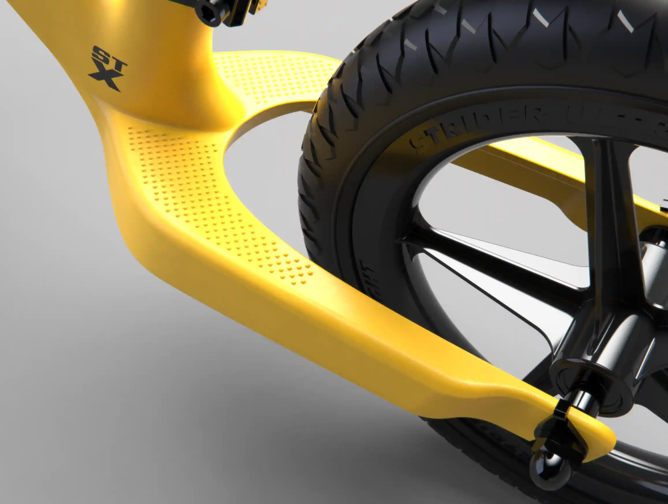
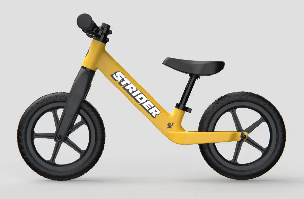
Round 2: Surface Tension. Refining the highlights. We moved into Class-A surfacing, defining the "transition zones" where surfaces meet to create tension in the lines so the bike looked fast even when standing still.
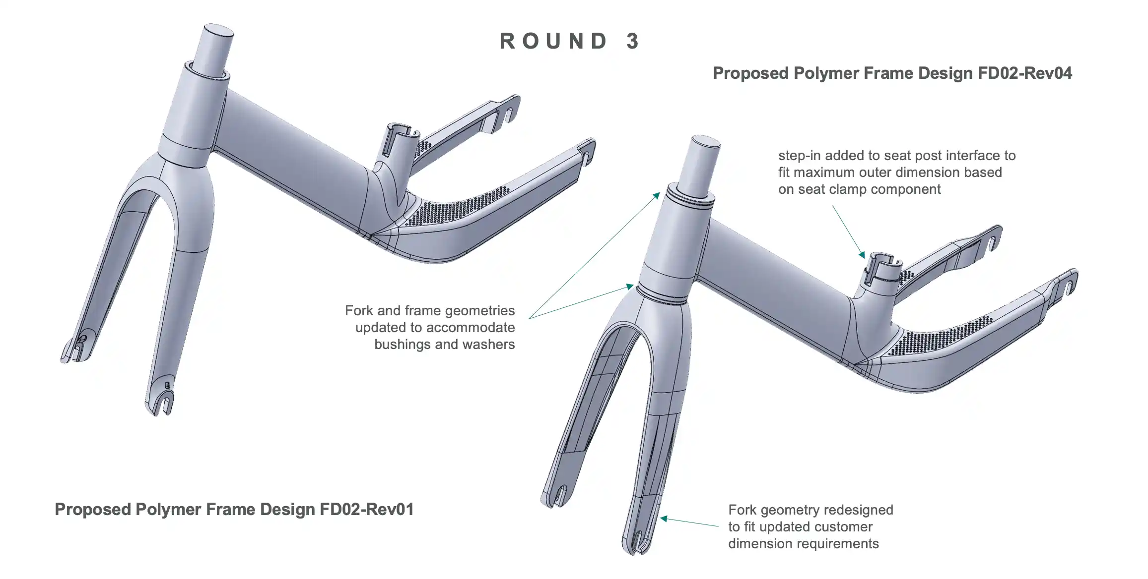
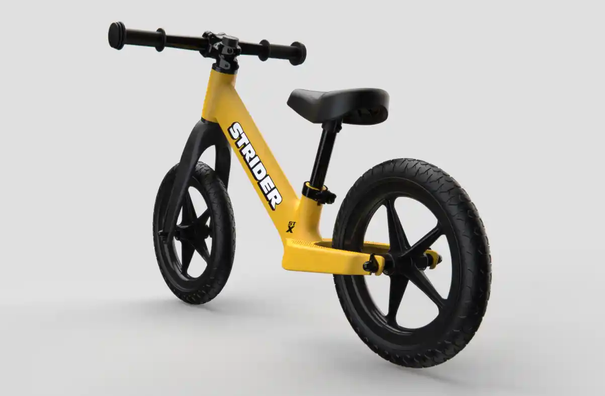
Round 3: Production Readiness. Finalizing for the mold. This phase involved applying draft angles, checking wall thickness, and ensuring all parting lines were hidden or integrated into the aesthetic flow.
We worked closely with engineering to verify the design against strict Factor of Safety requirements.
By utilizing Finite Element Analysis (FEA), we were able to strategically place internal ribbing to handle load paths without
creating sink marks on the exterior Class-A surfaces.
This iterative loop allowed us to reduce overall part weight while
maximizing stiffness, ensuring the bike performs as aggressively as it looks.
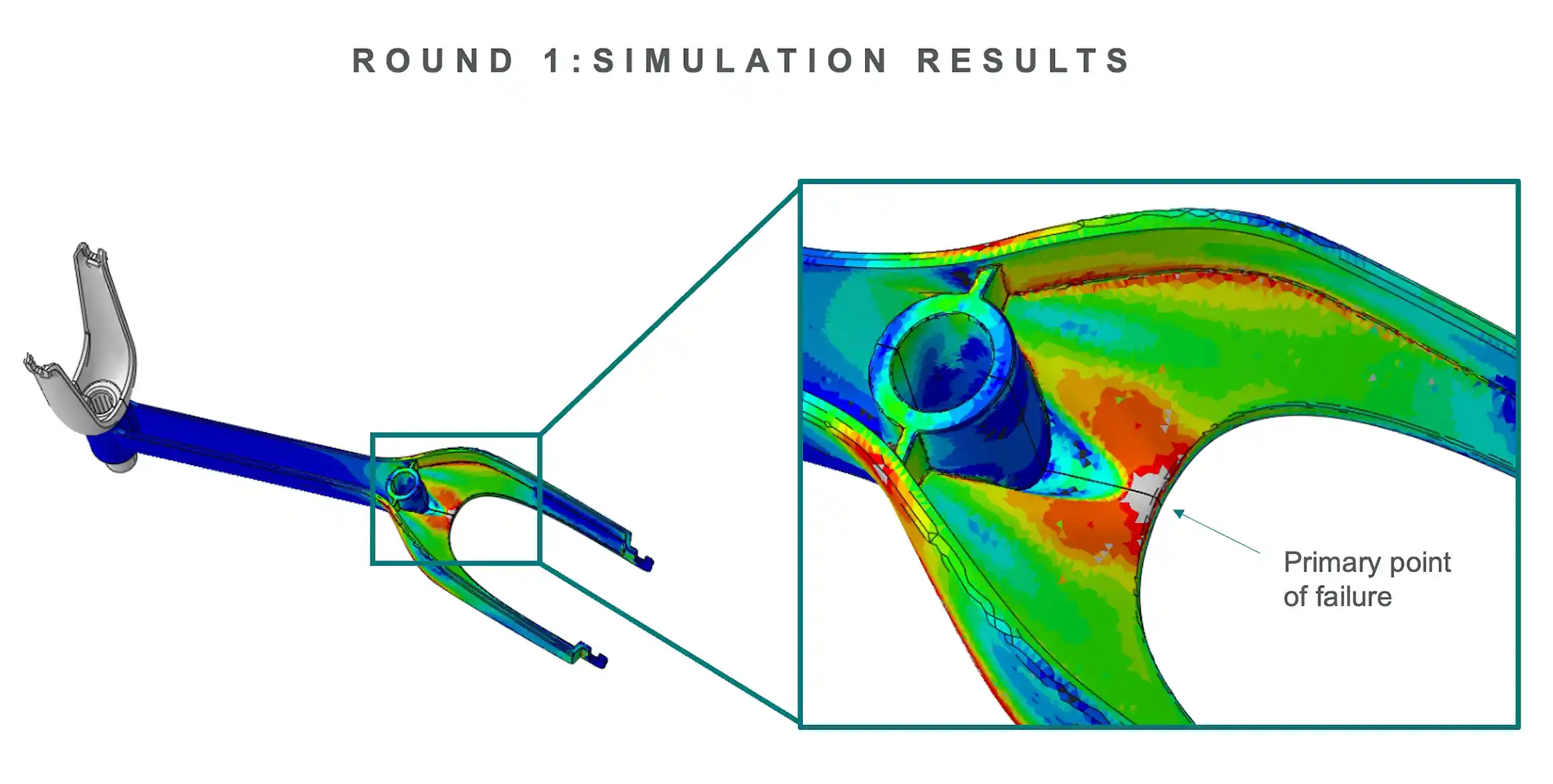
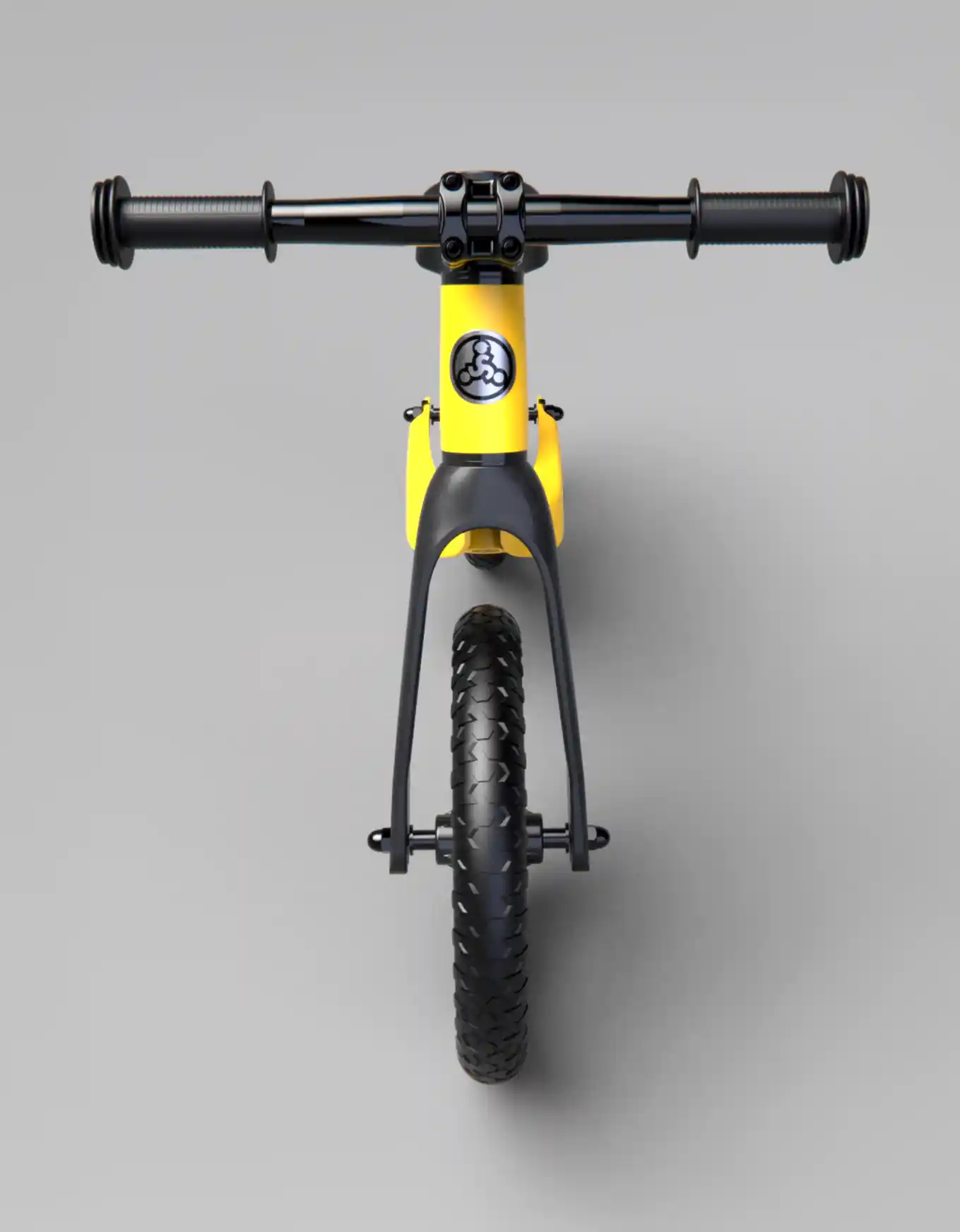
The initial analysis revealed a critical stress concentration at the fork yoke. The hollow shell design lacked the internal stiffness to handle vertical loads, falling below the required Factor of Safety.
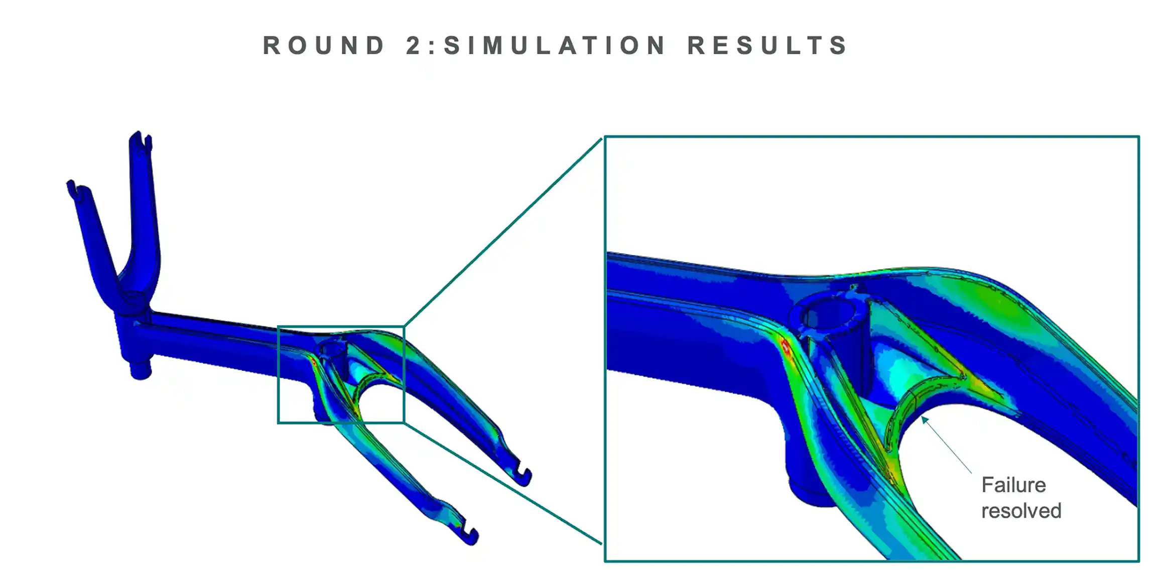
We integrated a targeted internal ribbing pattern to redistribute the load paths. This resolved the structural failure and met all safety standards without adding sink marks to the exterior Class-A surface.
Although strategic shifts paused the program prior to mold cutting, the design phase was a technical success. This final visualization represents the fully engineered assembly—validated for draft, wall thickness, and assembly constraints—proving that the "Carbon Aesthetic" was fully achievable in mass-production plastics.